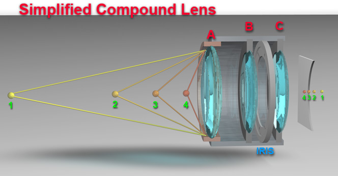
A compound lens is made up of two or more lenses, sometimes they are referred to as groupings. The lens below shows three groups A, B, and C. (In a more realistic compound lens each of these groups would likely contain a series of mixed convex, and concave lenses, but we are going to simplify it here!)
All of the lens groups are located in the lens barrel (the external cylinder) and in this case there are two fixed lenses (B and C) that never move. These lenses maintain a constant distance from the film/ccd plane at all times. There is a third lens (A) which is used to focus on the outside world. It focuses at different distances by moving along the lens barrel parallel to the optical axis. (Optical axis - an imaginary line connecting points 1-2-3-4)
Without going into the math and geometry, the fixed lenses serve a couple of purposes. From previous slides it has been shown that a lens will focus a real world object at its equivalent distance behind the lens. This is not good for a camera, it might require some really thick cameras to get the film plane back far enough for some far objects. The stationary lenses reduce the focal range of the real world to a more manageable width. In this example the external world points 1-2-3-4 (left side) are both reduced in size and will now focus across the range of points 1-2-3-4 on the right side. The range is compressed. As the focus lens (A) is moved along the body, it can focus on any selected point in the real world, and thus bring into focus that point on the film plane. It changes the A-B distance and brings each of the smaller 1-2-3-4 points (right side) on to the film plane for proper focus. In the diagram it would be focused approximately on point 3 which is roughly at the film plane.
The larger size of lens A also means it will gather more light, and produce brighter images. The contrast ratio will be increased.
A small movement in lens A will have little effect on that angle for a point located at a distance (1). For example, the angles produced for point 1 changes very little when lens A is moved throughout its range of motion. The resultant circles of confusion remain roughly constant, so a slight change in focus has little effect on sharpness.
As objects get closer to the front lens, the angle between the outside of the lens and the object increases. From the previous page we know that this pulls the focal point on the opposite side of the lens closer to the lens and produces a much wider circle of confusion for the light focused near the edges. If the lens were focused on point 4, then moving lens (A) only slightly would result in a much larger change in angle and thus a wider change in the circles of confusion. Hence in closeup work, the closer the object is to the lens the narrower the true focus range becomes. Or as we say it has decreased depth of focus.
For a given magnification, a longer lens with greater working distance will provide better depth of focus. Assuming a lens is capable of producing a 1:1 magnification (roughly equal sized image to the real world object), then a 200mm macro lens will produce better depth of field than 105mm macro, which will produce better depth of field than a 55mm macro.
For even higher magnifications (like in a microscope) the working distance is always far more limited, and optics are much smaller in size. The smaller size means less light capture (darker images). The smaller size also usually means thicker lenses which tend to produce higher focal angles. Thus in microscopic work the depth of focus is very shallow.
|
Typical depth of field numbers (in mm)
|
 |
||||
|
Reproduction Ratio
(magnification) |
f/5.6
|
f/8
|
f/11
|
f/16
|
|
|
1:4 (25%)
|
7.5
|
10.6
|
14.6
|
21
|
|
|
1:2 (50%)
|
2.25
|
3.2
|
4.4
|
6.4
|
|
|
1:1 (100%)
|
0.75
|
1.07
|
1.47
|
2.14
|
|
|
2:1 (200%)
|
0.28
|
0.4
|
0.55
|
0.8
|
|
|
3:1 (300%)
|
0.16
|
0.24
|
0.32
|
0.47
|
|
|
4:1 (400%)
|
0.11
|
0.17
|
0.23
|
0.34
|
|
|
5:1 (500%)
|
0.09
|
0.13
|
0.18
|
0.25
|
|
|
10:1 (10x)
|
0.030
|
0.052
|
0.106
|
0.21
|
|
|
20:1 (20x)
|
0.0135
|
0.025
|
0.050
|
0.10
|
|
|
30:1 (30x)
|
0.009
|
0.017
|
0.033
|
0.066
|
|
 |
|||||
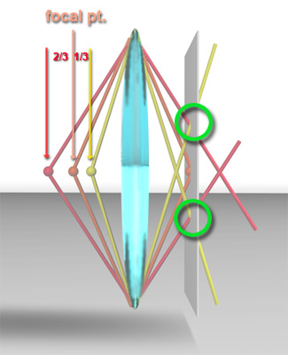
The diagram to the right illustrates why this happens. The orange sphere represents the point focused upon, and the yellow sphere represents the nearest area still in focus. If you place the reddish sphere at 2x the distance behind the focus point, the diagram shows the resultant focal cross-over points on the film/ccd. Notice that the yellow cross-over points and the red cross-over points strike the plane of focus exactly at the same spot. (Green circles)
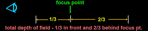
Since both cross-over points produce identical circles of confusion they are both equally in-focus at this point. Thus the 1/3 and 2/3 distances describe the total field of focus. This assumes that the circles of confusion at this point are just below the optical threshold for the human eye and thus everything appears in-focus.